- What is a Multiplexer?
- What is a Demultiplexer?
- Difference Between Multiplexer And Demultiplexer Overview
- Differences Between Multiplexer And Demultiplexer (Comparison Table)
- Multiplexer Types
- Advantages and Disadvantages of Multiplexer
- Applications of Multiplexers
- Types of Demultiplexer
- Advantages and Disadvantages of Demultiplexer
- Applications of Demultiplexer
- Summary: Multiplexers vs Demultiplexers in Digital Systems
- Conclusion
Demystifying The Differences Between Multiplexers And Demultiplexers
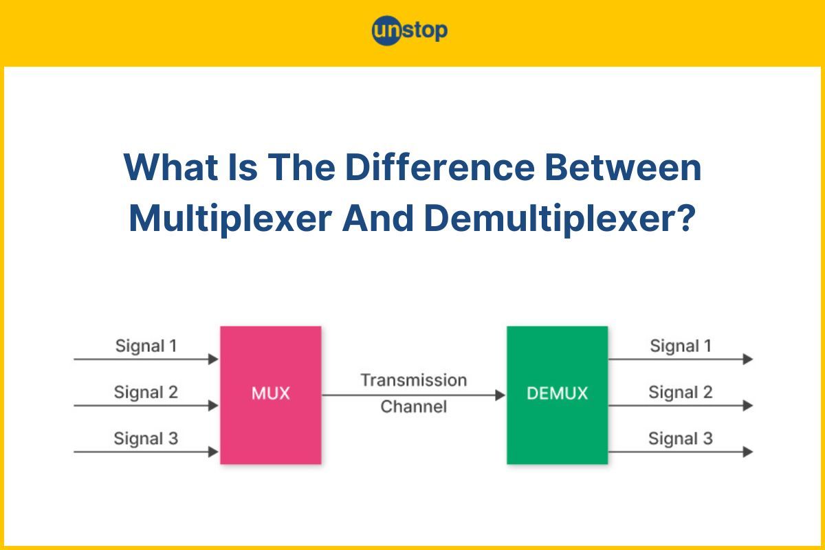
Multiplexers and demultiplexers are quite prevalent in network transmission, communications systems, or digital electronics. They form the building blocks of digital systems and are used for digital signal processing. In this article we will discuss the difference between multiplexer and demultiplexer, but first, let’s look at some basics about the devices individually.
What is a Multiplexer?
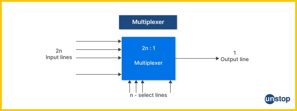
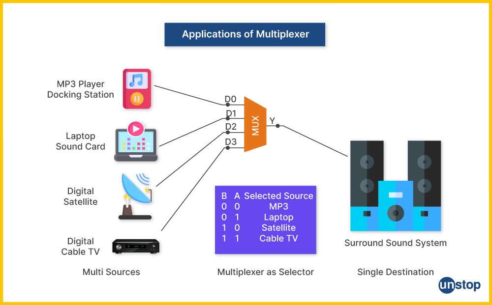
A multiplexer (MUX) is a digital device that allows several data sources to share one channel. It takes input from various sources, such as audio or video signals, and combines them into one line for transmission. Multiplexers use select lines to determine which input will get switched to output.
- Multiplexers are commonly used in communications systems for combining different information streams into a single stream of bits which can then be sent over a medium such as fibre optic cable or copper wire.
- They also allow users to access multiple devices using only one computer port. For example, instead of connecting four devices through Ethernet cables, they could connect all four through just one USB connection by utilizing a USB hub and an appropriate type of multiplexer.
- Multiplexers consist of two main components– an encoder circuit at the sending end and a decoder circuit at the receiving end.
- The encoder section receives inputs from each source individually and selects which signal it should send out next, based on control logic set in advance by the user - for instance, deciding between sending audio versus video information first if both incoming streams were competing simultaneously.
- It then transmits this output after converting it into serial form through modulation techniques such as frequency-division multiplexing (FDM). At its destination point, however, these encoded packets must be reassembled back into their original form for interpretation and display, which is where the decoder comes in.
In general, multiplexers are responsible for allowing multiple devices to share a single communication channel and providing improved transmission efficiency by packaging data together based on its type or origin before sending it through the line.
They're also important components of digital networks as they enable them to transfer large amounts of information quickly without congesting their available bandwidth capacity, making them essential elements within any internet infrastructure set up today.
Now that we know about multiplexers let's discuss what are demultiplexers before diving into the difference between multiplexer and demultiplexer.
What is a Demultiplexer?
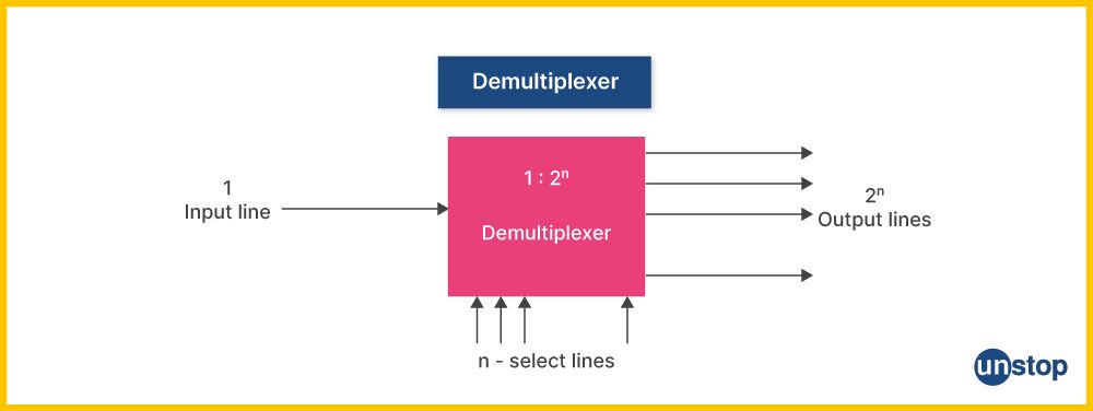
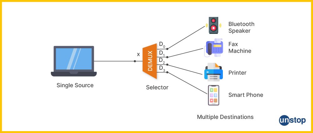
A demultiplexer is a device that takes one data input line and directs it to multiple output lines. It can be seen as the inverse of a multiplexer, which combines two or more signals into one signal for transmission over a single channel or medium.
- Demultiplexers are used in communication systems such as digital subscriber loops (DSL) and cable television systems, where they allow for efficient use of limited bandwidth channels by allowing several lower-bandwidth streams to share them simultaneously.
- In practical terms, a demultiplexer is like an electronic switchboard: it takes an incoming signal with one frequency at its inputs and divides this up into separate outputs based upon different select codes associated with each output port; these select codes determine which information gets sent through which port at any given time.
- For example, if you wanted three different video feeds on your TV set-top box coming from three separate satellite dishes but only had space on your cable connection for one feed, then you would need some way of dividing those images up so each dish could send its unique image down onto the same wire.
Inputs in a demultiplexer are typically binary control signals, often referred to as select lines that determine what output is selected; they may also require enable-level and/or signal-level input to operate correctly.
These inputs act like electronic switches (in some cases physically moving parts within the device), which open up different paths for data depending on whether there's an 'on' or 'off' state present at each point along those pathways; only when these states match will they enable passage from one end of their circuitry to another essentially allowing specific outputs access whilst blocking others simultaneously.
Difference Between Multiplexer And Demultiplexer Overview
A multiplexer is an electronic device that combines two or more input signals into a single output signal. It allows for efficient data transmission by allowing several channels to occupy one line and transport them as one entity, thus reducing the need for additional gates and communications links.
On the other hand, a demultiplexer separates those same combined signals from the source back into its components, such as analog/digital audio-video signals being broadcast through satellite radio or TV platforms.
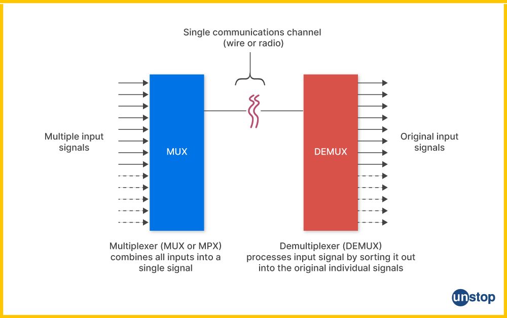
The major difference between multiplexer and demultiplexer is in how they deal with their incoming information.
- Multiplexers combine information onto parallel streams going outwards. Demultiplexers separate this combination to bring it back into its originally separated parts at each location, where it needs to be used separately again.
- Multiplexers require an externally applied control signal which determines what portion of the channel's bandwidth should be allocated (or transmitted) when transmitting a particular type of signal, like video or audio. In contrast, demultiplexers contain internal logic circuitry that automatically detects and decodes any received signal without requiring external control input bits. Rather it relies on pattern-matching algorithms based on reverse process and conversion technique.
- Multiplexers are used mostly within fibre link signals-based communication systems as it helps in combining numerous constituent signals into a single mainstream that can be transmitted over long distances. In contrast, demultiplexer generally employs a multi-position switch mechanism to "unpack" these combined information streams, thus enabling them for proper utilization at each endpoint device.
Differences Between Multiplexer And Demultiplexer (Comparison Table)
The table below lists the difference between multiplexer and demultiplexer across categories:
|
Category |
Multiplexer |
Demultiplexer |
|
Definition |
The circuit that accepts multiple inputs but presents only a single output is known as the multiplexer. |
The circuit that accepts only a single input signal and presents multiple outputs is the demultiplexer. |
|
Commonly known as |
The multiplexer is commonly known as a data selector, as it selects from various digital input signals. |
The demultiplexer is commonly known as a data distributor. |
|
How does it act? |
It works as a digital switch. |
These circuits work as digital circuits. |
|
Number of Input and Output |
These circuits have multiple inputs of data and/or signals. |
These circuits have multiple outputs of data and/or signals. |
|
Conversion technique |
These circuits accept parallel to serial conversion. |
These circuits accept serial to parallel conversion. |
|
Operating Principle |
Multiplexer works with the principle of many-to-one. |
Demultiplexers operate under the one-to-many principle. |
|
Uses |
Multiplexer is used in signal transmission data compression and channel sharing. |
Demultiplexer is used for signal routing duplication and distribution. |
|
Types |
They are of many types, like 2 to 1, 8 to 1, 16 to 1, etc. |
They are of many types, like 1 to 2, 1 to 8, 1 to 16, etc. |
Multiplexer Types
There are numerous types of multiplexers, depending on the application and the required input lines. For example, a 2-to-1 multiplexer has 2 input lines, one select line, and one output line. There is always one output line in a multiplexer. Some common types of digital multiplexers are:
- 2-to-1 Multiplexer: A 2-to-1 multiplexer combines two input signals into one output signal. It involves selecting the two inputs based on a control signal and determining which input gets passed through to the output.
- 4-to-1 Multiplexer: This combines four input signals into one output signal using the abovementioned principle for 2-to-1 multiplexing. The control line will have two bits, in this case representing different combinations, to select any of the four inputs and route it to the output.
- 8-to-1 Multiplexer: With eight inputs and one output, an 8-to-1 multiplexer allows selection between multiple data sources or channels by utilizing three select lines or address bits. These select lines determine which input is connected to the common output line.
- 16-to-1 Multiplexer: A 16-inputs to one-output configuration requires four address bits or select lines that can provide up to sixteen unique combinations corresponding to each possible chosen input source at any given time.
Multiplexing Types
Multiplexing involves combining two or more analog and/or digital signals into one output signal. Different types of multiplexing techniques also exist for transmitting signals over a single communication channel. Some of these techniques are:
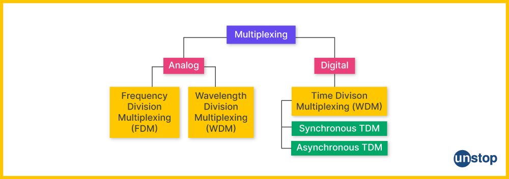
1. Time-Division multiplexing (TDM)- Time-Division multiplexing is used to manage a high volume of information flow. Multiplexers divide time among n communication channels, allotting equal amounts of time for each channel without interruption from the others. Listed below are two types of TDM: Synchronous Multiplexing and Asynchronous Multiplexing.
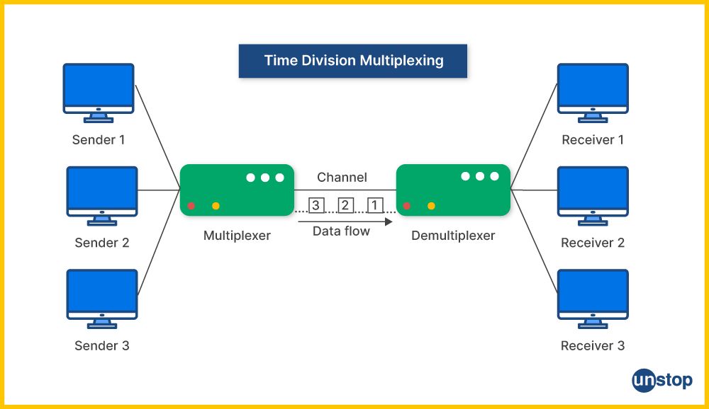
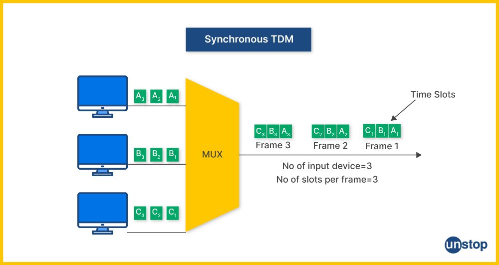
a. Synchronous Multiplexing: Synchronous multiplexers operate using time slots instead of individual frequencies like their counterparts do in asynchronous systems. Since both receivers and transmitters are simultaneously exchanging information back and forth over one physical link, it allows large amounts of information transfer with less crosstalk interference from adjacent channels. This makes synchronous multiplexing more reliable for high-speed transmissions such as TDM/DS0 lines providing up to 64 Kbps per channel.
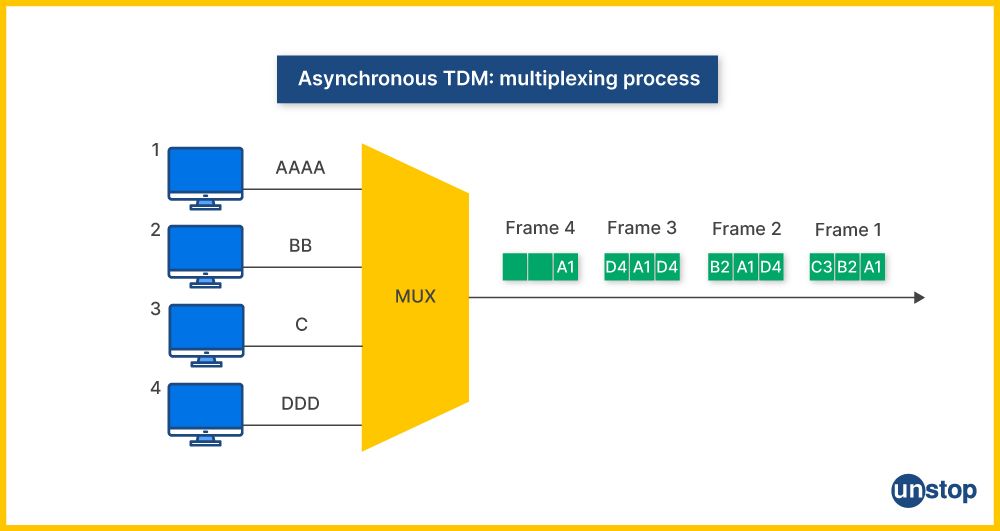
b. Asynchronous Multiplexing: Asynchronous multiplexers (AMUXs) allow transferring digital information at differing rates from different sources on one physical link by using time division techniques to share bandwidth between senders and receivers efficiently. This type allows more efficient use compared to synchronous, where all users must communicate at the same rate or suffer possible lost packets. With asynchronous multiplexing, user speeds are not linked together, allowing for faster downloads. Even if slower uploads may lag, it does not disrupt transmission flow due to this independent control.
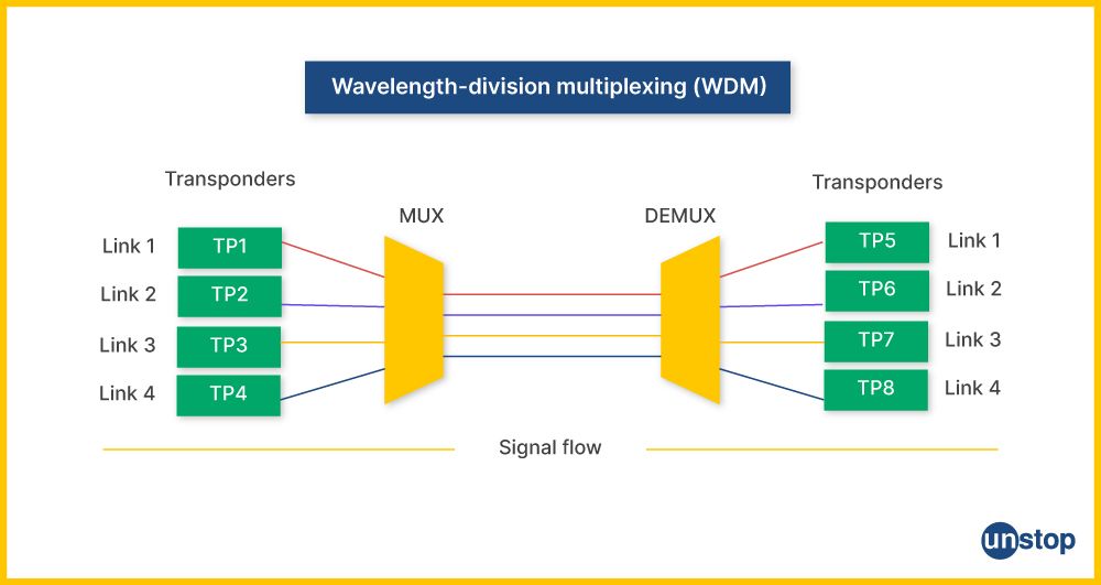
2. Wavelength Division Multiplexing (WDM): WDM combines different types of data signals on the same fibre-optic cable. It assigns a unique wavelength, or colour, to each signal travelling through the optical network. Doing so allows multiple streams of data to be sent at once without interference between them. Each stream will have its dedicated frequency that can travel along with other signals within the system uninterrupted and uncorrupted by others sharing the same line.
Coarse Wavelength Division Multiplexing (CWDM) and Dense Wavelength Division Multiplexing (DWDM) are two wavelength patterns employed by WDM. CWDM utilizes multiple transmission windows in silica fiber to provide 18 channels, while DWDM concentrates on the c-band window.
3. Frequency Division Multiplexing (FDM): Frequency Division Multiplexing divides the frequency spectrum among a number of narrowband carrier frequencies, enabling simultaneous transmission and reception without carrier interference. It uses different frequencies but operates in the same area.
In addition to these, there are also different methods for multiplexing light signals over an optical fiber link, like optical time-division multiplexing (OTDM), code division multiplexing (CDM), etc.
In optical time-division multiplexing, a multiplexer optically modulates numerous single signals and forms a composite optical signal.
In code division multiplexing, light signals are multiplexed by using different coding schemes. CDM is more secure than other methods but also a lot more complex and expensive.
Advantages and Disadvantages of Multiplexer
In this section, we'll take a look at some of the major advantages and disadvantages of using a multiplexer:
Advantages of Multiplexer:
- Cost-effective: Multiplexers save costs by combining several communication channels into one single channel, thereby reducing the number of cables and other hardware components required for data transmission.
- Increased efficiency: Multiplexers allow different types of signals, such as audio, video and digital signals to be processed parallelly or simultaneously on a shared medium instead of having them sequentially transmitted. This leads to better utilization rates.
- Improved scalability: It's easy to add more devices to an existing network using a multiplexer without needing additional wiring or equipment modification. Thus, it helps reduce overall maintenance costs associated with scaling up networks over time due to increased customer and user demand.
Disadvantages Of Multiplexer
The disadvantages of multiplexers include the following:
- Limited bandwidth availability: Only limited bandwidth is available for each signal carried through the multiplexed line. Thus, A multiplexer is unsuitable when a large amount of data needs to be quickly transferred from source point A To Point B.
- Susceptible to noise interference: Since there’s no guarantee that all lines carrying the same type of information will have the same quality, if some line gets affected the entire stream could get disrupted due to noise interference resulting in loss of data or information.
- Security issues: As multiplexers are used to combine several communication channels into a single channel, it increases the risk of hacking. Because there’s an easy access point for hackers to break in and cause security threats.
Applications of Multiplexers
Let's take a look at some of the major applications of multiplexers:
- Digital systems: Multiplexers are used to select one of several available communication paths or signals and transmit it over a single channel for digital systems like CPUs, computers, etc.
- Networking applications: Multiplexers are also used in networking solutions such as Ethernet switches which allow multiple devices to communicate on the same network by selecting the appropriate line for each device.
- Audio-video broadcasting: In audio-visual broadcasting, multiplexes can be used to receive channels from different satellite transponders at once using only one receiver box with its antenna pointed towards a single satellite dish instead of having individual receivers separately pointing towards the direction of every transponder.
- Automotive applications: Multiplexing is also used in automotive engineering, where different signals from a vehicle's sensors and controllers are combined into one digital signal for communication over the onboard computer network.
- Telecommunications: In telecommunications, multiplexers can combine several low-speed data streams into high-speed channels, which can then be sent down a physical single transmission channel such as copper wires or fiber optics cables at a much faster speed than with separate communications links.
- Line Sharing: In telephone networks, multiplexers are used for line sharing between different devices, such as fax machines and telephones. A multiplexer can be integrated into a complex network to determine which device has priority line access.
Types of Demultiplexer
Just like there exist different types of multiplexers depending on input lines, there are different types of demultiplexers depending on the output lines and application. These are:
1. 1-to-2 Demultiplexer: To cut down on the amount of data lines by one bit, a 1 to 2 demultiplexer is used. It is a combinational logic circuit. It generates two digital outputs based on the input's value using a single input signal. Logic applications and memory decoding frequently use 1-to-2 demultiplexer.

2. 1-to-4 Demultiplexer: A 1-to-4 demultiplexer is a circuit that enables switching between four different outputs using a single digital signal. It is controlled by two control lines (A and B) and one input line (Data D). Control lines are also referred to as selection lines.
Based on the values of the control lines, one of the four outputs (Y0, Y1, Y2, Y3) will be randomly selected.

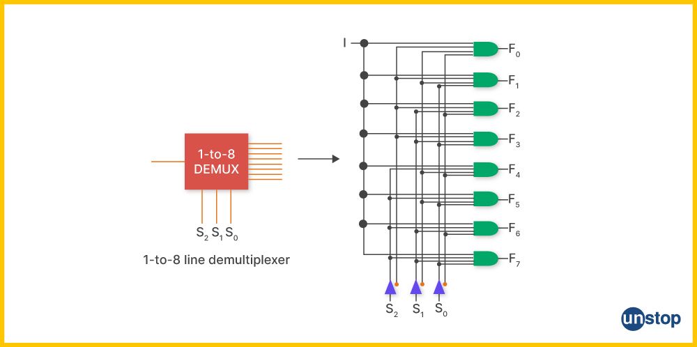
3. 1 to 8 Demultiplexer: A demultiplexer 1-to-8 is a combinational logic circuit. It accepts an input signal and, depending on the value of the input, generates eight outputs. The majority of its uses are in digital logic.
4. 1-to-16 Demultiplexer: A demultiplexer is a combinatorial logic circuit that cuts the number of data lines by one bit. It is available in the range of 1-to-16. The following demultiplexer circuit diagram contains four control lines (S0, S1, S2, S3), one input line (A), and 16 outputs (Y0-Y15). Depending on the input and control lines, one of the 16 outputs is chosen for that specific input. It is mostly utilized in logic and memory decoding applications.
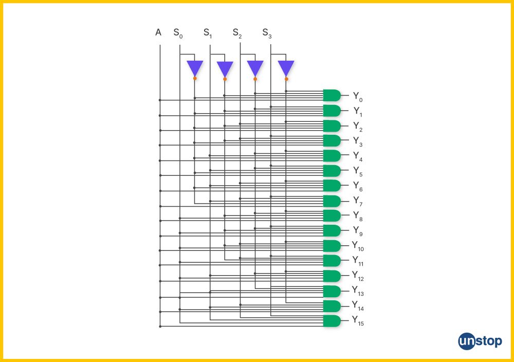
In a digital circuit, the process of demultiplexing involves taking one data input and routing it to multiple outputs based on the selector inputs.
Advantages and Disadvantages of Demultiplexer
There are several advantages and disadvantages of using a demultiplexer, as listed below:
Advantages of a Demultiplexer:
- Cost-effective: Demultiplexers allow large amounts of data to be transmitted over a single line, thus making it extremely cost-effective and time-saving for businesses that need to transfer large quantities of information on a regular basis.
- Reliability: The demultiplexer is much more reliable than many other types of multiplexers since it only requires one connection in order to send the signals rather than several different ones, as with other systems.
- Reduces Interference: It can also help reduce interference from adjacent signal sources, which makes communication more secure and reliable and less susceptible to errors caused by external influences like electromagnetic radiation or changes in voltage levels along the network path between sender and receiver devices.
Disadvantages of a Demultiplexer:
- Latency: As with any system, there is always some latency associated when transmitting data. However, this will depend largely on the type of device used and its configuration settings; if poorly configured, then it can result in longer wait times, leading to slower throughput speeds and delays during transmission processes.
- Cost: Depending on the required size and functionality, demultiplexers can be expensive due to their intricate circuitry and components.
- Signal Degradation: Each time a signal goes through a demultiplexer, there is potential for signal degradation or loss due to imperfections in circuit elements such as resistance, capacitance, or noise introduced during transmission.
- Technical Complexity: Due to the complexity of setting up and configuring demultiplexers, it can be difficult for those without technical knowledge or experience in this area to effectively use demultiplexers.
Applications of Demultiplexer
Let's take a look at some of the major applications of demultiplexers:
- Increasing the number of output lines: Demultiplexers can split one data line into multiple, processing more data at once and increasing the system's throughput.
- Data Encryption: When powerful encryption algorithms are employed in communication networks, demultiplexer devices are used for input partitioning, which is vital for secure transmission over public networks or internet mediums.
- Optical Networking Applications: In optical networking systems, demuxes perform an important task, converting signals from single fibre optics links into individual channels that may be distributed further through copper wires. This technology allows a huge amount of digital information across various geographical locations while securing privacy and preventing crosstalk between channels.
- High-speed communication: Demuxes are commonly used in high-speed communication links such as T1, E1, etc., to split the incoming data stream into multiple streams for further processing and analysis.
Summary: Multiplexers vs Demultiplexers in Digital Systems
To sum it up, here's a look at the primary use and difference between multiplexer and demultiplexer in digital systems.
Multiplexer and Demultiplexer: Primary Use
A multiplexer (MUX) is a digital logic circuit that combines multiple input signals into one output signal. A demultiplexer (DeMUX) is an electronic device that operates opposite to the MUX - it takes a single input line and produces several outputs according to pre-specified selection lines.
Multiplexers and demultiplexers are primarily employed in digital communication systems for effective data encoding and decoding between two devices on various networks. Instead of having dedicated cables for each connection point, it is possible to dramatically boost total bandwidth utilization by combining multiple low-speed channels or independent lines carrying different types of information onto one high-speed network line.
Difference Between Multiplexer and Demultiplexer Explained
- Number of channels: Multiplexers can handle multiple input channels and output a single channel, while demultiplexers can handle a single input channel and output multiple channels.
- Control input: A multiplexer has a single control input that selects which input channel to transmit, whereas a demultiplexer has multiple control inputs, each selecting which output channel receives the input.
- Signal loss: Multiplexing can cause signal loss or degradation due to combining signals, but demultiplexing only divides and distributes the original signal resulting in minimal loss or degradation.
- Applications: Multiplexers are used in signal transmission, data compression, and sharing limited communication resources. Demultiplexers are used to efficiently route signals to different destinations by duplicating or distributing the incoming information.
- Implementation: Both multiplexers and demultiplexers can be implemented using logic gates like AND, OR, NOT (for multiplexer) and NAND, NOR, XOR (for demultiplexer).
- Types: 4:1 multiplexer, 8:1 multiplexer, 16:1 multiplexer; 1:4 demultiplexer, 1:8 demultiplexer, 1:16 demultiplexer
Conclusion
The multiplexer and demultiplexer are two complementary devices that work together in digital systems to enable efficient data transmission. Both circuits act as electronic switchboards for sending information efficiently over limited bandwidth resources or long distances through mediums such as fibre optics cables or copper wires without disrupting source signals.
They also help reduce crosstalk between different channels while providing increased scalability and security features for enterprise networks within their respective designs. Additionally, they eliminate the need for several individual lines for each separate signal or channel, reducing the cost associated with communications networks.
Suggested Reads:
- 8 Highest Paying Jobs For Computer Science Professionals In India
- Test Plan vs Test Strategy: What Makes The Two Different?
- The Difference Between Static And Dynamic Website Explained!
- Difference Between Mealy Machine And Moore Machine [With Comparison Table]
- Advantages And Disadvantages Of Computer Network (& More) Explained
I’m a reader first and a writer second, constantly diving into the world of content. If I’m not writing or reading, I like watching movies and dreaming of a life by the beach.
Login to continue reading
And access exclusive content, personalized recommendations, and career-boosting opportunities.
Subscribe
to our newsletter




Comments
Add comment